
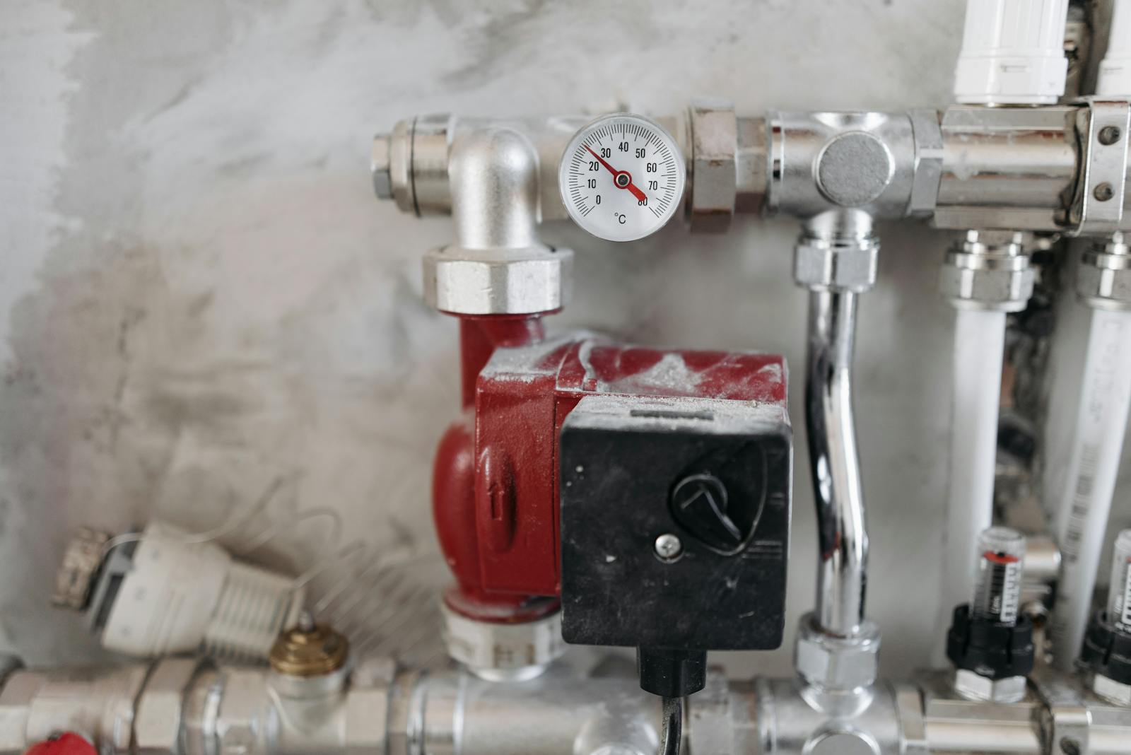
Hydronic water balancing brings every coil, circuit setter, and pump in a chilled or heating-water loop into compliance with the engineer’s GPM and delta-T schedule. We perform this work under ASHRAE 111 and the NEBB and AABC procedural standards using ultrasonic flow meters, differential-pressure gauges, and pump performance verification against manufacturer curves.
What hydronic balancing verifies
- Measured GPM at every coil, balancing valve, and circuit setter, against design
- Measured pump head, motor amperage, and operating point on the manufacturer curve
- Loop delta-T at full load and minimum load conditions
- Three-way valve travel and balancing-valve setting documentation
- Air vent function, expansion tank charge, and strainer pressure drop
When hydronic balancing is required
New construction closeout, chiller or boiler replacement, pump or coil retrofit, ASHRAE 90.1 energy verification, LEED Energy and Atmosphere submittals, and any chronic delta-T or comfort issue on an existing loop.
What you receive
A stamped report with every measured value next to design intent, pump curves with operating points plotted, calibration certificates, photo documentation of any deficiency, and a punch list for the mechanical contractor.
What our hydronic water balancing report delivers
Specifically, our hydronic water balancing report opens with the project metadata, then covers every coil, pump, and balancing valve with measured GPM next to design GPM. Furthermore, the hydronic water balancing report includes pump curve operating points and identifies any device requiring re-trim. Therefore, the document closes out the mechanical scope and feeds commissioning verification on the water-side.
Industry standards on the water-side
The water-side of a commercial HVAC system is governed by ASHRAE Guideline 22 (instrumentation), ASHRAE 90.1 (energy), and the engineer’s project-specific design narrative. Pump curves come from the manufacturer; operating points are field-verified against the curve. Balancing valves come in many flavors — circuit setters, automatic flow limiters, pressure-independent control valves, triple-duty valves — each with its own setting procedure. Ultrasonic flow meters are used where insertion is impractical (high-rise risers, energized circuits, no-shutdown projects). The crew matches instrument to system every time.
Talk to us
Send the mechanical drawings and a schedule outline and you will hear back within one business day with a fixed-price proposal.
Request a proposal Call 800-883-6040
What hydronic water balancing verifies on commercial loops
Specifically, hydronic water balancing under ASHRAE 111 verifies GPM at every coil, pump head and curve operating point, and balancing-valve setpoints across chilled-water, hot-water, and condenser loops. Then the report ties every measured deficiency back to a specific device — circuit setter, triple-duty, or VFD. Furthermore, our hydronic water balancing crew uses ultrasonic flow meters where insertion is impractical.
When commercial projects require hydronic water balancing
First, every commercial closeout with a hydronic loop needs hydronic water balancing for the AHJ. Additionally, retrofits that add or replace coils, pumps, or valves trigger a discrete hydronic water balancing scope. Therefore, the smart owner ties it to the mechanical substantial-complete milestone.
Our hydronic water balancing field procedure
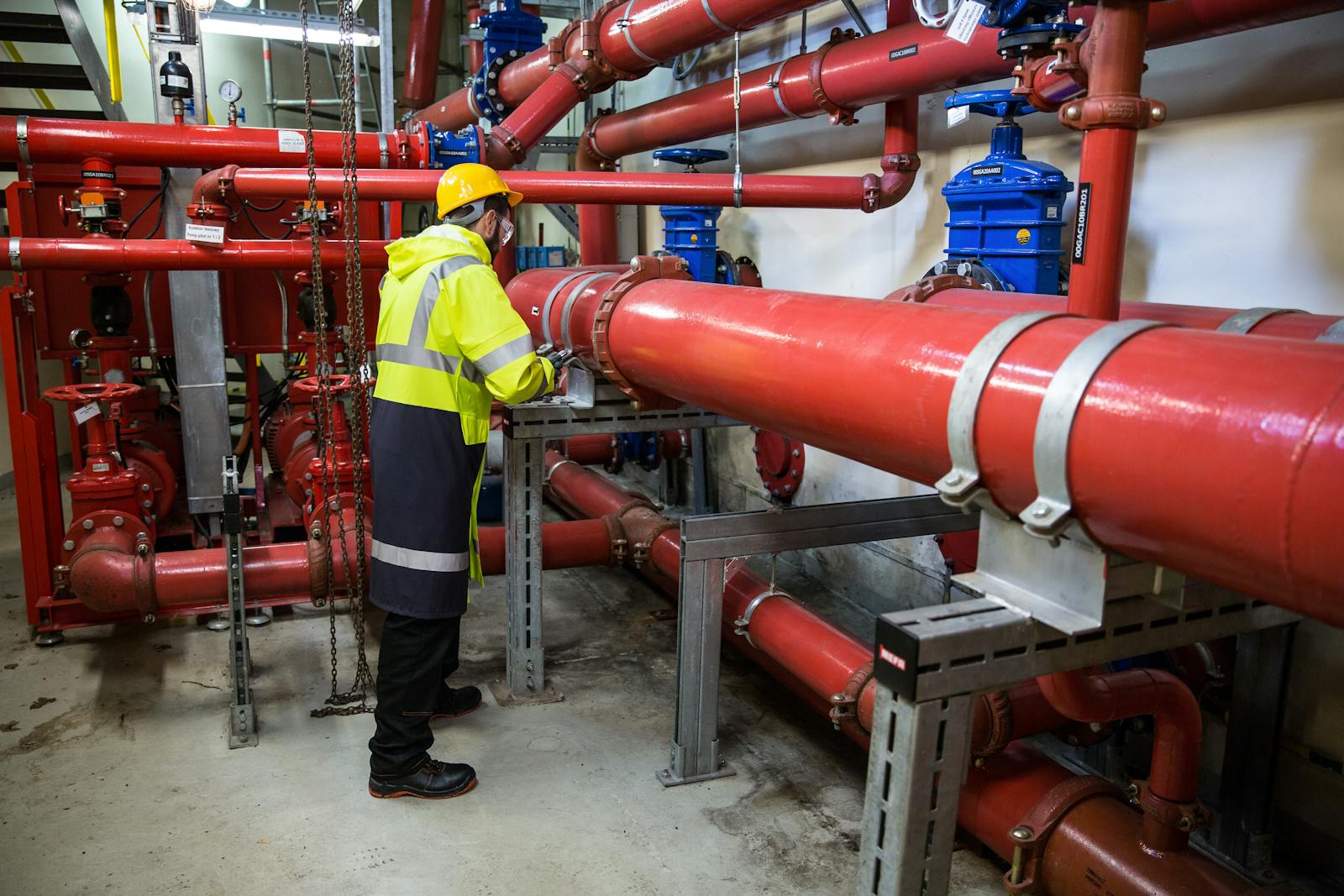
First, our hydronic water balancing crew arrives after the mechanical contractor confirms loop fill and pump start-up. Then we calibrate pressure gauges and ultrasonic flow meters. After that, our hydronic water balancing process verifies pump curve operating points, then sets every balancing valve to deliver design GPM at every coil. Furthermore, every hydronic water balancing measurement is logged with timestamp, technician initials, and instrument calibration date.
Related resources
Related services
- Commercial air balancing — air-side TAB for the same building
- HVAC commissioning — whole-system verification including hydronics
Further reading
Industry standards & references
- AABC — Associated Air Balance Council
- NEBB — National Environmental Balancing Bureau
- ASHRAE Standards (Standard 111 — TAB)